Tutorial 8 : Basic shading
In this 8th tutorial, we will learn how to do some basic shading. This includes :
- Beeing more bright when closer to a light source
- Having highlights when looking in the reflection of a light (specular lighting)
- Beeing darker when light is not directly towards the model (diffuse lighting)
- Cheating a lot (ambient lighting)
This does NOT include :
- Shadows. This is a broad topic that deserves its own tutorial(s)
- Mirror-like reflections (this includes water)
- Any sophisticated light-matter interaction like subsurface scattering (like wax)
- Anisotrophic materials (like brushed metal)
- Physically based shading, which tries to mimic the reality closely
- Ambient Occlusion (it’s darker in a cave)
- Color Bleeding (a red carpet will make a white ceiling a litte bit red)
- Transparency
- Any kind of Global Illumination whatsoever (it’s the name that regroups all previous ones)
In a word : Basic.
Normals
During the last few tutorials you’ve been dealing with normal without really knowing what they were.
Triangle normals
The normal of a plane is a vector of length 1 that is perpendicular to this plane.
The normal of a triangle is a vector of length 1 that is perpendicular to this triangle. It is easily computed by taking the cross product of two of its edges (the cross product of a and b produces a vector that is perpendicular to both a and b, remember ?), and normalized : its length is brought back to 1. In pseudo-code :
triangle ( v1, v2, v3 )
edge1 = v2-v1
edge2 = v3-v1
triangle.normal = cross(edge1, edge2).normalize()
Don’t mix up normal and normalize(). Normalize() divides a vector (any vector, not necessarily a normal) by its length so that its new length is 1. normal is just the name for some vectors that happen to represent, well, a normal.
Vertex normals
By extension, we call the normal of a vertex the combination of the normals of the surroundings triangles. This is handy because in vertex shaders, we deal with vertices, not triangles, so it’s better to have information on the vertex. And any way, we can’t have information on triangles in OpenGL. In pseudo-code :
vertex v1, v2, v3, ....
triangle tr1, tr2, tr3 // all share vertex v1
v1.normal = normalize( tr1.normal + tr2.normal + tr3.normal )
Using vertex normals in OpenGL
To use normals in OpenGL, it’s very easy. A normal is an attribute of a vertex, just like its position, its color, its UV coordinates… so just do the usual stuff. Our loadOBJ function from Tutorial 7 already reads them from the OBJ file.
GLuint normalbuffer;
 glGenBuffers(1, &normalbuffer);
 glBindBuffer(GL_ARRAY_BUFFER, normalbuffer);
 glBufferData(GL_ARRAY_BUFFER, normals.size() * sizeof(glm::vec3), &normals[0], GL_STATIC_DRAW);
and
 // 3rd attribute buffer : normals
 glEnableVertexAttribArray(2);
 glBindBuffer(GL_ARRAY_BUFFER, normalbuffer);
 glVertexAttribPointer(
     2,                                // attribute
     3,                                // size
     GL_FLOAT,                         // type
     GL_FALSE,                         // normalized?
     0,                                // stride
     (void*)0                          // array buffer offset
 );
and this is enough to get us started.
The Diffuse part
The importance of the surface normal
When light hits an object, an important fraction of it is reflected in all directions. This is the “diffuse component”. (We’ll see what happens with the other fraction soon)
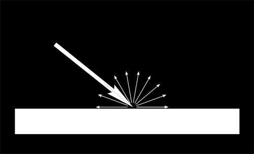
When a certain flux of light arrives at the surface, this surface is illuminated differently according to the angle at which the light arrives.
If the light is perpendicular to the surface, it is concentrated on a small surface. If it arrives at a gazing angle, the same quantity of light spreads on a greater surface :
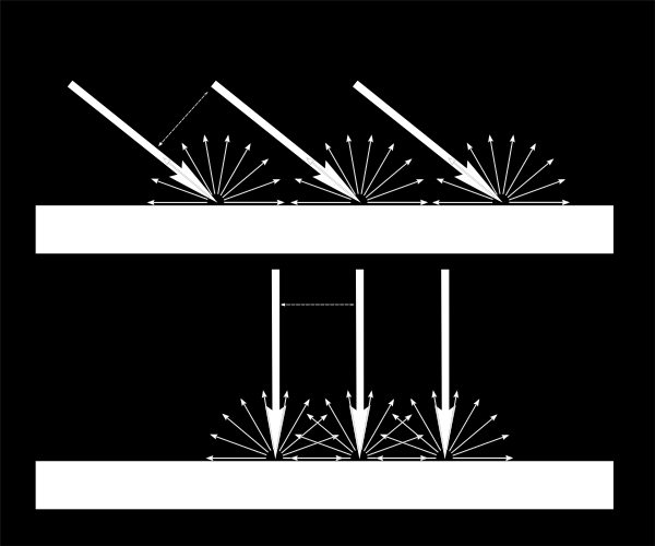
This means that each point of the surface will look darker with gazing light (but remember, more points will be illuminated, so the total quantity of light will remain the same)
This means that when we compute the colour of a pixel, the angle between the incoming light and the surface normal matters. We thus have :
// Cosine of the angle between the normal and the light direction,
// clamped above 0
//  - light is at the vertical of the triangle -> 1
//  - light is perpendicular to the triangle -> 0
float cosTheta = dot( n,l );

color = LightColor * cosTheta;
In this code, n is the surface normal and l is the unit vector that goes from the surface to the light (and not the contrary, even if it’s non inuitive. It makes the math easier).
Beware of the sign
Something is missing in the formula of our cosTheta. If the light is behind the triangle, n and l will be opposed, so n.l will be negative. This would mean that colour = someNegativeNumber, which doesn’t mean much. So we have to clamp cosTheta to 0 :
// Cosine of the angle between the normal and the light direction,
// clamped above 0
//  - light is at the vertical of the triangle -> 1
//  - light is perpendicular to the triangle -> 0
//  - light is behind the triangle -> 0
float cosTheta = clamp( dot( n,l ), 0,1 );

color = LightColor * cosTheta;
Material Color
Of course, the output colour also depends on the colour of the material. In this image, the white light is made out of green, red and blue light. When colliding with the red material, green and blue light is absorbed, and only the red remains.
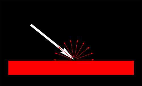
We can model this by a simple multiplication :
color = MaterialDiffuseColor * LightColor * cosTheta;
Modeling the light
We will first assume that we have a punctual light that emits in all directions in space, like a candle.
With such a light, the luminous flux that our surface will receive will depend on its distance to the light source: the further away, the less light. In fact, the amount of light will diminish with the square of the distance :
color = MaterialDiffuseColor * LightColor * cosTheta / (distance*distance);
Lastly, we need another parameter to control the power of the light. This could be encoded into LightColor (and we will in a later tutorial), but for now let’s just have a color (e.g. white) and a power (e.g. 60 Watts).
color = MaterialDiffuseColor * LightColor * LightPower * cosTheta / (distance*distance);
Putting it all together
For this code to work, we need a handful of parameters (the various colours and powers) and some more code.
MaterialDiffuseColor is simply fetched from the texture.
LightColor and LightPower are set in the shader through GLSL uniforms.
cosTheta depends on n and l. We can express them in any space provided it’s the same for both. We choose the camera space because it’s easy to compute the light’s position in this space :
// Normal of the computed fragment, in camera space
 vec3 n = normalize( Normal_cameraspace );
 // Direction of the light (from the fragment to the light)
 vec3 l = normalize( LightDirection_cameraspace );
with Normal_cameraspace and LightDirection_cameraspace computed in the Vertex shader and passed to the fragment shader :
// Output position of the vertex, in clip space : MVP * position
gl_Position =  MVP * vec4(vertexPosition_modelspace,1);

// Position of the vertex, in worldspace : M * position
Position_worldspace = (M * vec4(vertexPosition_modelspace,1)).xyz;

// Vector that goes from the vertex to the camera, in camera space.
// In camera space, the camera is at the origin (0,0,0).
vec3 vertexPosition_cameraspace = ( V * M * vec4(vertexPosition_modelspace,1)).xyz;
EyeDirection_cameraspace = vec3(0,0,0) - vertexPosition_cameraspace;

// Vector that goes from the vertex to the light, in camera space. M is ommited because it's identity.
vec3 LightPosition_cameraspace = ( V * vec4(LightPosition_worldspace,1)).xyz;
LightDirection_cameraspace = LightPosition_cameraspace + EyeDirection_cameraspace;

// Normal of the the vertex, in camera space
Normal_cameraspace = ( V * M * vec4(vertexNormal_modelspace,0)).xyz; // Only correct if ModelMatrix does not scale the model ! Use its inverse transpose if not.
This code can seem impressive but it’s nothing we didn’t learn in Tutorial 3 : Matrices. I paid attention to write the name of the space in each vector’s name, so that keeping track of what is happening is much easier. You should do that, too.
M and V are the Model and View matrices, which are passed to the shader in the exact same way as MVP.
Time for work
You’ve got everything you need to code a diffuse lighting. Go ahead, and learn the hard way :)
Result
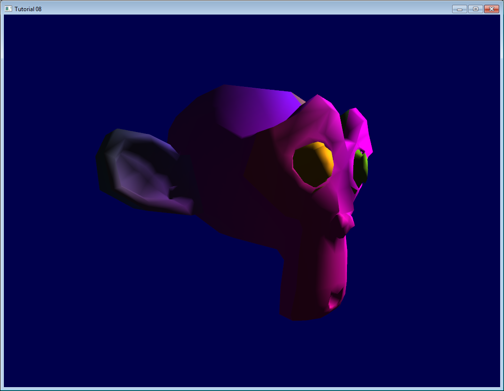
With only the Diffuse component, we have the following result (sorry for the lame texture again) :
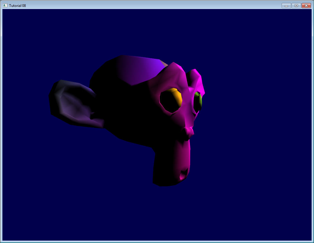
It’s better than before, but there is still much missing. In particular, the back of Suzanne is completely black since we used clamp().
The Ambient component
The Ambient component is the biggest cheat ever.
We expect the back of Suzanne to be receive more light because in real life, the lamp would light the wall behind it, which would in turn (slightly less) light the back of the object.
This is awfully expensive to compute.
So the usual hack is to simply fake some light. In fact, is simply makes the 3D model *emit *light so that it doesn’t appear completely black.
This can be done this way :
vec3 MaterialAmbientColor = vec3(0.1,0.1,0.1) * MaterialDiffuseColor;
color =
 // Ambient : simulates indirect lighting
 MaterialAmbientColor +
 // Diffuse : "color" of the object
 MaterialDiffuseColor * LightColor * LightPower * cosTheta / (distance*distance) ;
Let’s see what it gives
Results
Ok so that’s a little bit better. You can adjust the (0.1, 0.1, 0.1) if you want better results.
The Specular component
The other part of light that is reflected is reflected mostly in the direction that is the reflection of the light on the surface. This is the specular component.
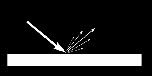
As you can see in the image, it forms a kind of lobe. In extreme cases, the diffuse component can be null, the lobe can be very very very narrow (all the light is reflected in a single direction) and you get a mirror.
(we can indeed tweak the parameters to get a mirror, but in our case, the only thing we take into account in this mirror is the lamp. So this would make for a weird mirror)
// Eye vector (towards the camera)
vec3 E = normalize(EyeDirection_cameraspace);
// Direction in which the triangle reflects the light
vec3 R = reflect(-l,n);
// Cosine of the angle between the Eye vector and the Reflect vector,
// clamped to 0
//  - Looking into the reflection -> 1
//  - Looking elsewhere -> < 1
float cosAlpha = clamp( dot( E,R ), 0,1 );

color =
    // Ambient : simulates indirect lighting
    MaterialAmbientColor +
    // Diffuse : "color" of the object
    MaterialDiffuseColor * LightColor * LightPower * cosTheta / (distance*distance) ;
    // Specular : reflective highlight, like a mirror
    MaterialSpecularColor * LightColor * LightPower * pow(cosAlpha,5) / (distance*distance);
R is the direction in which the light reflects. E is the inverse direction of the eye (just like we did for “l”); If the angle between these two is little, it means we are looking straight into the reflection.
pow(cosAlpha,5) is used to control the width of the specular lobe. Increase 5 to get a thinner lobe.
Final result
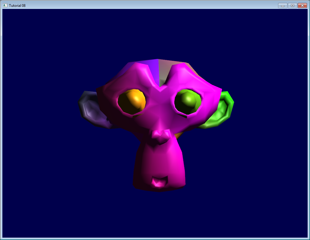
Notice the specular highlights on the nose and on the eyebrows.
This shading model has been used for years due to its simplicity. It has a number of problems, so it is replaced by physically-based models like the microfacet BRDF, but we will see this later.
In the next tutorial, we’ll learn how to improve the performance of your VBO. This will be the first Intermediate tutorial !